


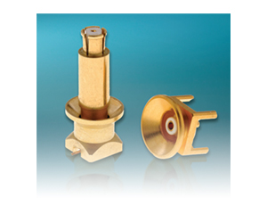
SMPM / SMP / SMP-LOCK / SMP-COM / SMP-MAX
| Type | Descriptions | General | Application | Data Sheet | ||
| SMP | Radiall SMP series meets MIL STD 348, figure 326 interface standard
and DESC specifications 94007 & 94008. They are intermateable with
GPO® (Gilbert Engineering Inc.). There are 3 levels of retention (applicable to the male connectors when ordering) which provide different levels of force required to connect and disconnect the connectors: - full detent for a positive locking with a maximum retention - limited detent for a positive locking with a medium retention - smooth bore for the lowest retention (slide connection) |
50Ω | DC - 40GHz |
- Small, lightweight connectors - Snap-in, suitable for blindmate applications - Excellent vibration and shock performances - Allows axial and radial misalignment |
- Active array antenna - Satellite - Airborne - Ship - Ground radar - Communication - High speed electro-optical devices - Board to boardapplications |
다운로드 |
| SMP-COM | SMP-COM is an economically priced alternative fully intermateable with standard SMP connectors. It has been optimized to operate
up to 12.4 GHz meeting the needs of telecom applications.
Compared to SMP primarily made of stainless steel material, SMP-COM uses brass material. |
DC - 12.4 GHz |
||||
| SMPM | 30% smaller than SMP, SMPM connectors are designed for very high frequency applications where space and package density
are a necessity. Radiall SMPM series meets MIL STD 348, figure 328 interface standard. They are intermateable with GPPO®. There are 2 levels of retention (applicable to the male connectors when ordering): - full detent for a positive locking with a maximum retention - smooth bore for a lower retention but higher durability |
DC- 65GHz |
||||
| SMP-LOCK | Radiall has expanded its broad range of SMP products with SMP-LOCK connectors featuring a robust locking mechanism, which dramatically
increases the retention force of the interface and prevents accidental disconnection. They have been specially designed for harsh environments and to withstand more severe vibration and drop tests. SMP-LOCK connectors are suitable for cable-to cable or cable-to-module interconnections insid equipment subject to harsh mechanical stress. |
- Two step connection, low insertion force - Audible click indicates that plug is locked,eliminating accidental disconnections - Locking sleeve provides greater retention force more than 450N with RG-405 cable - SMP interface has DC-40 GHz - Plug equipped with EMI ring offers improved RFleakage performance -92dB at 18 GHz |
- Airborne radars - Avionics - Satellites - Missile - UAV - UGV |
다운로드 | ||
| SMP-MAX | From base stations to repeaters and even handheld and GPS devices, we have a tailored connector solution for you ; | 50Ω | DC- 6 GHz |
- Microminiature coaxial connectors - Power up to 300 Watts - Board to board distance misalignment of at least 0.078’’ (2.0 mm) - Tilt (radial misalignment): 3° minimum - 1.2 max VSWR at DC-3GHz |
- Broadcast - RF components (filters, amplifiers, .. ) - Wireless Communications |
|
| MMBX | The MMBXTM connector series is particularly suitable for board to board connection in new generation telecommunication systems. MMBXTM connectors allow a quick connection in a minimum space requirement. Frequency range is DC to 12.4 GHz. SMT connectors are totally compatible with pick and place machines. |
50Ω | DC- 12.4 GHz |
- Snap-on mating - Microminiature coaxial connectors - Robust - Surface mount receptacles - Fully compatible with automated pick and place machines |
- Board to board applications - Base station - High density packaging |
다운로드 |
| MCX | The MCX series utilizes the SMB series electrical line and features a particularly simple, compact and robust interface. The MCX series is 30 % smaller than the SMB. The MCX series helps to miniaturize equipment. It lowers wiring connection costs through its full crimp and solder crimp versions as the centre contact of the straight models can be either crimped or soldered. It optimizes PCB layouts with its range of models for PCBs including surface mount and press-fit receptacles. |
50Ω 75Ω |
DC- 6 GHz |
- Subminiature coaxial connectors - "Push-pull" snap-on mating - Complies with specification CECC 22220 - CEI standard 1169-36 |
50Ω models - Wireless communications - Civil and military radio - telecom equipment 75Ω models - Video communication - Television broadcasting |
|
| BMR-SPRING | The high-performance and robust BMR-Spring can handle a minimum board to board (or rack and panel) distance tolerance of 2 mm with custom misalignment of 3mm or more. It also features a 6°tilt. It has an operating frequency range of DC-8 GHz, a 1.1 max VSWR guaranteed up to 3 GHz, and it can handle up to 350 watts of powerat 2.7 GHz. BMR-Spring also features a unique non-slotted spherical interface for improved electrical performance, high vibration and shock resistance, and an 80dB of shielding up to 3 GHz. A self-alignment mechanism makes the BMR-Spring particularly ruggedized for blind- mate applications. The spring-loaded adapters are symmetrical to avoid any assembly issues. |
50Ω | DC- 8 GHz |
- Robust - High power up to 350W at 2.7 GHz - Board to board distance misalignment at least 0.078” (2 mm), custom misalignment of 3 mm+ - Tilt misalignment 6°max |
- Broadcast - RF components - Wireless communications - Military equipment |
|
MOEBIUS Characteristics
| Not mated | Mated | |
| Operating temperature range | -40°C to + 110°C | |
| Rated power | 10 W / 900 MHz | |
| DC Current Withstanding | 1 A max | |
| Frequency range | DC to 6 GHz | |
| V.S.W.R. | 1.20 max DC to 3 GHz 1.50 max 3 to 6 GHz |
1.15 max DC to 3 GHz 1.25 max 3 GHz to 6 GHz |
| Insertion loss | 0.15 dB max DC to 2 GHz 0.20 dB max 2 GHz to 3 GHz 0.40 dB max 3 GHz to 6 GHz |
0.10 dB max DC to 2 GHz 0.15 dB max 2 GHz to 3 GHz 0.20 dB max 3 GHz to 6 GHz |
| Isolation loss | - | 35 dB minDC to 1 GHz 25 dB min 1 GHz to 3 GHz 25 dB min 3 GHz to 6 GHz |
| Item | Specification | Conditions |
| Contact resistance | 200 mΩ max | 100 mA |
| Insulation resistance | 3000 MΩ min | 250 V DC |
| Withstanding voltage | No flashover or insulation breakdown |
250 V rms |
| Vibration | No discontinuities > 1μs under 100mA |
Sinus: 5-500Hz / displacement 0.75 peak / acceleration 10 g duration 2h in each direction Random: 5-1000Hz / displacement 0.75 peak / acceleration 3.3 g duration 1h in each direction 25 dB min 3 GHz to 6 GHz |
| Shock | No discontinuities > 1μs under 100mA |
Acceleration 50 g / duration pulse 11 ms / wave-form pulse half sinus / number of shocks 3 per direction |
| Free fall | Center contact resistance RF measurements No discontinuities > 1 ms under 100mA |
NFC 20732 method 1 Test area concrete / fall height 1 m / duration 2*2 falls |
| Temperature life | Center contact resistance RF measurements |
T + 90°C / duration 1000 h / 40% HR |
| Thermal shock | Center contact resistance RF measurements |
T - 40°C to + 90°C Exposure 15mn / transfert time < 10 s / 100 cycles |
| Damp heat | Center contact resistance RF measurements |
40°C / 93% / 21 days |
| Retention Force Insertion Force - mating Extraction Force - unmating |
9N 12N | Initial |
| Durability | Mating – unmating force Center contact resistance RF measurements |
25.000 cycles |
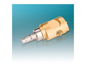
RF Power 스위칭 커넥터 (Switching Connector)
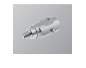
QMA 타입
| QMA 타입 전기적 특성 | ||
| Impedance | 50Ω | 데이터 시트 다운로드 |
| Frequency range | DC - 3 GHz | |
| Typical V.S.W.R. | 1.1 + 0.1000 x F (GHz) Maxi | |
| Isolation at • DC to 1 GHz • 1 to 2 GHz • 2 to 3 GHz |
-47 dB typical -43 dB typical -40 dB typical |
|
| Insertion Loss at • DC to 1 GHz • 1 to 2 GHz • 2 to 3 GHz |
0.1 dB maxi 0.15 dB maxi 0.2 dB maxi |
|
| RF leakage | NA | |
| Voltage rating | 300 Veff maxi | |
| Dielectric withstanting voltage | 500 Veff mini | |
| Insulation resistance | 5000 MΩ mini | |
| Power withstanding | 110 W (at 2 GHz) | |
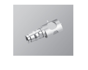
N 타입
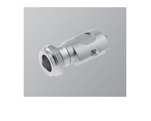
| N 타입 전기적 특성 | ||
| Impedance | 50Ω | 데이터 시트 다운로드 |
| Frequency range | DC - 3 GHz | |
| Typical V.S.W.R. | 1.1 + 0.1000 x F(GHz) Maxi | |
| Isolation at • DC to 1 GHz • 1 to 2 GHz • 2 to 3 GHz |
-47 dB typical -43 dB typical -40 dB typical |
|
| Insertion Loss at • DC to 1 GHz • 1 to 2 GHz • 2 to 3 GHz |
0.1 dB maxi 0.15 dB maxi 0.2 dB maxi |
|
| RF leakage | NA | |
| Voltage rating | 300 Veff maxi | |
| Dielectric withstanting voltage | 500 Veff mini | |
| Insulation resistance | 5000 MΩ mini | |
| Power withstanding | 100 W (at 0.9 GHz and 1.8 GHz) | |
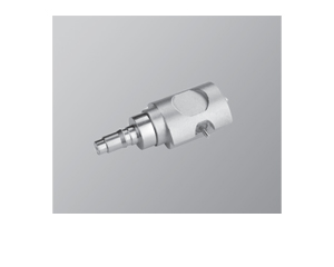
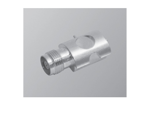
SMA 타입
| SMA 타입 전기적 특성 | ||
| Impedance | 50Ω | 데이터 시트 다운로드 |
| Frequency range | DC - 3 GHz | |
| Typical V.S.W.R. | 1.1 + 0.1000 x F (GHz) Maxi | |
| Isolation at • DC to 1 GHz • 1 to 2 GHz • 2 to 3 GHz |
-47 dB typical -43 dB typical -40 dB typical |
|
| Insertion Loss at • DC to 1 GHz • 1 to 2 GHz • 2 to 3 GHz |
0.1 dB maxi 0.15 dB maxi 0.2 dB maxi |
|
| RF leakage | NA | |
| Voltage rating | 300 Veff maxi | |
| Dielectric withstanting voltage | 500 Veff mini | |
| Insulation resistance | 5000 MΩ mini | |
| Power withstanding | 80 W (at 0.9 GHz) 50 W (at 1.8 GHz) | |
QN 타입
| QN 타입 전기적 특성 | ||
| Impedance | 50Ω | 데이터 시트 다운로드 |
| Frequency range | DC - 3 GHz | |
| Typical V.S.W.R. | 1.1 + 0.09 x F (GHz) Maxi | |
| Isolation at • DC to 1 GHz • 1 to 2 GHz • 2 to 3 GHz |
-47 dB typical -43 dB typical -40 dB typical |
|
| Insertion Loss at • DC to 1 GHz • 1 to 2 GHz • 2 to 3 GHz |
0.1 dB maxi 0.15 dB maxi 0.2 dB maxi |
|
| RF leakage | NA | |
| Voltage rating | 300 Veff maxi | |
| Dielectric withstanting voltage | 500 Veff mini | |
| Insulation resistance | 5000 MΩ mini | |
| Power withstanding | 110 W (at 2 GHz) | |
TNC 타입
| TNC 타입 전기적 특성 | ||
| Impedance | 50Ω | 데이터 시트 다운로드 |
| Frequency range | DC - 3 GHz | |
| Isolation at • DC to 1 GHz • 1 to 2 GHz • 2 to 3 GHz |
-47 dB typical -43 dB typical -40 dB typical |
|
| Insertion Loss at • DC to 1 GHz • 1 to 2 GHz • 2 to 3 GHz |
0.1 √F (GHz) dB maxi 0.15 dB maxi 0.2 dB maxi |
|
| Voltage rating | 300 Veff maxi | |
| Power withstanding | 80 W (at 0.9 GHz) 50 W (at 1.9 GHz) | |