LOW PASSIVE INTERMODULATION TERMINATION
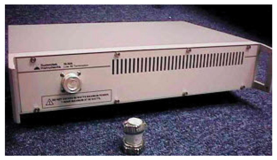
The SI-30A provides a means of terminating cables and test ports without generating significant levels of intermodulation products.
주요특징
- 400MHz capable
- Essential test environment accessory
기술 사양
SYSTEM
| Frequency range |
400MHz - 3600MHz |
| Characteristic impedance |
50ohms nominal |
| Return loss |
16dB minimum |
| Intermodulation products |
-120dBm (maximum, 2 x 20W carriers) | -125dBm, typical |
| Power handling |
75W average (minimum) |
| Connector |
DIN 7-16 jack |
| Recommended coupling torque |
30Nm (22 foot-pounds) |
| Maximum coupling torque |
50Nm (36 foot-pounds) |
MECHANICAL
| Dimensions H x D x W |
102 x 368 x 445mm | 4 x 14.5 x 17.5in |
| Weight |
8.2kg | 18.1lbs |
ENVIRONMENTAL
| Temperature range |
0ºC to +35ºC | +32°F to +95°F (operational) |
SUPPLIED ACCESSORIES
| DIN 7-16 plug-to-plug adapter |
|
ADDITIONAL PRODUCT OPTION
| SI-40A |
Includes the SI-30A plus two, 7-16 DIN male to N female adapters |
USING THE SI-30A
The SI-30A is designed to provide a minimum 16dB return loss from 400MHz to 3600MHz. The level of any single IM response generated in the reverse direction from the termination is less than -120dBm (-125dBm, typical) when two, 20W carriers are incident upon the termination.
Occasionally, the measured IM level from the termination may appear to exceed the -120dBm level. This can occur due to one or more of the following: |
| 1. |
The connector or device mating to the termination also has an approximate -118dBm IM level.This results in the IM from the termination and the connector adding in-phase to produce a resultant IM level as much as 6dB higher than any one device's individual IM level. |
| 2. |
The connector is not torqued properly. This results in partially mated electrical contacts within the connector. The termination's connector is designed for a coupling torque of 30 Newton-meters (approx. 22 foot-pounds). If "O"-rings are installed in the mating connector, or if the mating connector is designed for a higher coupling torque, up to 50 Newton-meters (approx 36 foot-pounds) may be used. Do not exceed this maximum torque as the termination's connector may be damaged. |
| 3. |
The connector is contaminated. Ensure both the termination's and the mating connector are clean and free of contaminants. Use a lint-free swab and alcohol to clean the interfaces, followed by a blast of clean air. |
| 4. |
The connector is excessively worn. After many mate and de-mate cycles, the connector on the termination may become worn. When the silver plating thins, this exposes metals which can produce an IM response. Please refer to the section below on replacing the connector on the SI-30A Termination. |
MAINTENANCE
| Step 1. |
Remove the top cover from the termination. Using a small, fine-toothed saw blade, cut the coaxial cable immediately behind the old connector. |
| Step 2. |
Remove the old connector from the termination housing. |
| Step 3. |
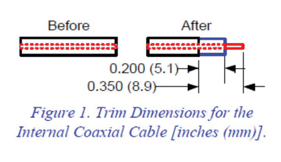
Trim the outer conductor from the resulting coaxial cable end 0.350 inches (8.9mm) as shown in Figure 1. Do not damage the dielectric of the cable while trimming. |
| Step 4. |
Trim the dielectric 0.20 (5.1 mm) inches from the jacket end as shown in Figure 1. Do not damage the center conductor while trimming. |
| Step 5. |
Using a fine-grit emery cloth (or Scotch-Brite™ pad), clean the outer conductor in the region where it will be soldered to the new connector. Lightly tin and then clean the outer conductor with flux-free solder wick. |
| Step 6. |
Pre-form the semi-rigid cable into the position it will be when finally soldered to the new connector. Be careful not to kink or stress the cable. |
| Step 7. |
Slide the sleeve over the prepared semi-rigid cable. Insert the semi-rigid cable into the new connector as far as it will go. While this cable is pressing against the connector, heat the center-contact while applying solder to the opposite side through the access hole until the solder flows around the center-conductor of the coaxial cable. |
| Step 8. |
Slide the sleeve over the connector to cover the access holes. Now heat the sleeve with an 800 Degree (F), 100W soldering iron. Apply solder to the joint to seal both the top and bottom of the sleeve to the connector body. |
| Step 9. |
Allow the assembly to cool. Install the panel mount connector into the termination housing. Install and tighten the four hex-head screws. |
| Step 10. |
Re-install the housing cover. |