


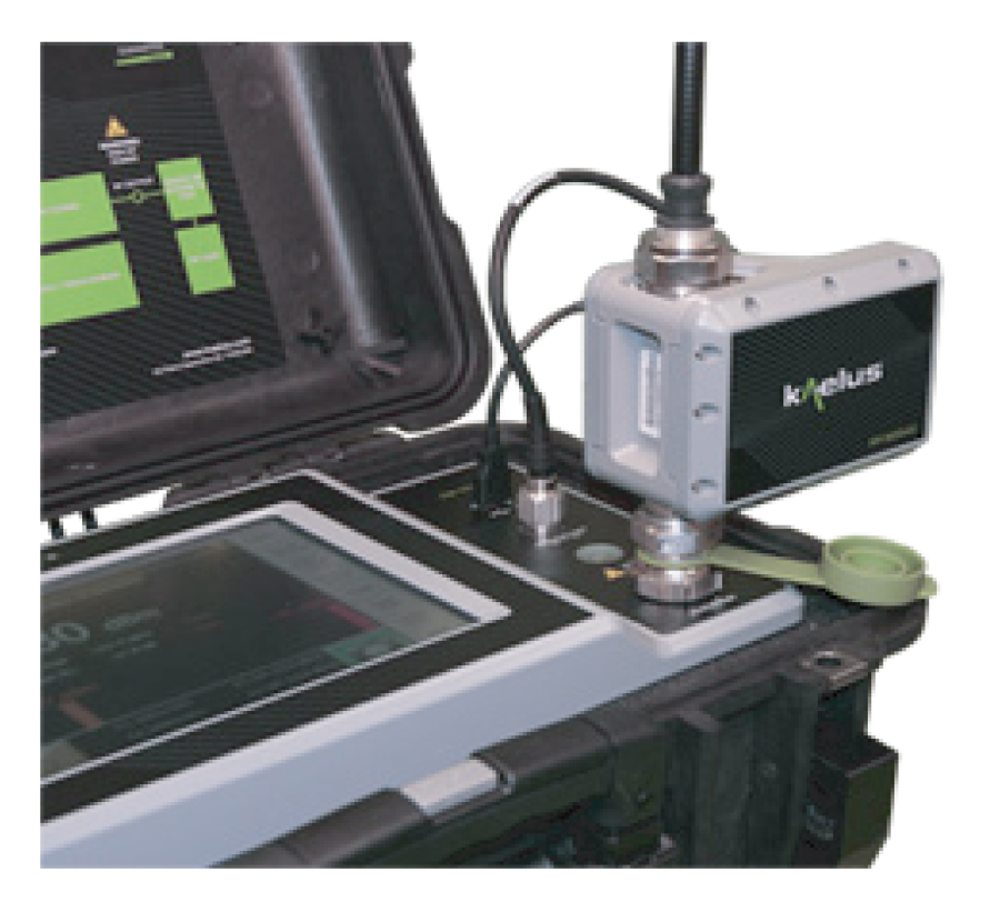
Range To Fault (RTF) is an exciting new technology from Kaelus that enables operators to accurately measure the location of PIM and Return Loss faults in their RF infrastructure. Reflection data together with PIM data provides an unmatched level of clarity for identifying the location of faults in the RF path. The RTF system consists of an RTF Module, interconnecting cables and a "RTF Enabled" iPA, iQA or iBA series PIM test instrument. Customers can purchase a new "RTF Enabled" PIM test analyzer from Kaelus or upgrade their existing A or B-series iQA test equipment to support RTF measurements. Please contact your local Kaelus representative for additional information.
| RTF analysis modes | Numeric: Distance to maximum PIM + PIM Magnitude Graphical: PIM vs. Distance, Return Loss vs. Distance, PIM + RL vs. Distance |
| Return loss | Max Return Loss (from FFT analysis) is displayed on the main PIM test screen when the RTF module is attached |
| Residual PIM | < -115dBm/-158dBc maximum (<-125dBm/-168dBc typical) @ 2 x +43dBm test tones |
| User interface ports | 1x USB, 1x Auxiliary port (Type N female) 1x RF output (7-16 DIN female), 1x RF input (7-16 DIN male) |
| Power | +12V DC supplied via auxiliary port |
| RF power (PIM) | 2x +43dBm supplied by iPA, iQA or iBA |
| RF power (Return Loss) | -35dBm supplied by RTF module (RTF-1000A and RTF-2000A), -20dBm (RTF-2600A) |
| Dimensions H x D x W | 127 x 90 x 73mm | 5.0 x 3.5 x 2.9in |
| Weight | 1.0kg | 2.2lbs |
| Temperature range | -10ºC to +40ºC | +14°F to +104°F |
| Ingress protection | IP50 (operating) |
| Operational humidity | 5% to 95% RH non-condensing |
| Storage temperature range | -20°C to +60°C | -4°F to +140°F |
| RTF MODULE | |||||||||||||||
| USB cable, Auxiliary port cable and carrying case included with RTF Module. A and B-series iQA PIM analyzers require a factory upgrade to be compatible with the RTF module. Contact Kaelus customer service to request an RMA number before returning equipment for upgrade. Upgrade part numbers are model and band specific. See list below for upgrade part number. |
|||||||||||||||
| MODEL | DESCRIPTION | IQA and IBA MODELS SUPPORTED | iPA MODELS SUPPORTED | ||||||||||||
| RTF-1000A | RTF Module, 698 - 960MHz | 0700L, 0700H, 0703, 0790, 0850, 0900, 0901 | 0707, 0703, 0790, 0850, 0900, 0901 | ||||||||||||
| RTF-2000A | RTF Module, 1710 - 2170MHz | 1800, 1900, 1921, 2101 | 1800, 1921, 2101 | ||||||||||||
| RTF-2600A | RTF Module, 2300 - 2700MHz | 2600 | 2600 | ||||||||||||
| IQA UPGRADE | |||||||||||||||
| *The iQA1921 operates over the PCS and AWS bands; however the RTF function is limited to the PCS band only. WARNING: Use of the portable PIM analyzer in a radiating mode, for example when connected to an antenna not enclosed in an anechoic environment, may be a violation of licensing regulations. Users should have permission in advance, from any licensed operators that might be affected by these tests. Furthermore, radiating high RF power can pose a personnel risk. Specifications subject to change without notice. | |||||||||||||||
| PART NUMBER | DESCRIPTION | ||||||||||||||
| RTF-U700LA | RTF upgrade for iQA-700LA analyzer | ||||||||||||||
| RTF-U700LB | RTF upgrade for iQA-700LB analyzer | ||||||||||||||
| RTF-U700HB | RTF upgrade for iQA-700HB analyzer | ||||||||||||||
| RTF-U850A | RTF upgrade for iQA-850A analyzer | ||||||||||||||
| RTF-U850B | RTF upgrade for iQA-850B analyzer | ||||||||||||||
| RTF-U900A | RTF upgrade for iQA-900A analyzer | ||||||||||||||
| RTF-U900B | RTF upgrade for iQA-900B analyzer | ||||||||||||||
| RTF-U901B | RTF upgrade for iQA-901B analyzer | ||||||||||||||
| RTF-U1800A | RTF upgrade for iQA-1800A analyzer | ||||||||||||||
| RTF-U1800B | RTF upgrade for iQA-1800B analyzer | ||||||||||||||
| RTF-U1921A* | RTF upgrade for iQA-1900A & iQA-1921A analyzers | ||||||||||||||
| RTF-U1921B* | RTF upgrade for iQA-1921B analyzers | ||||||||||||||
| RTF-U2101B | RTF upgrade for iQA-2101B analyzers | ||||||||||||||
When the RTF module is attached to the PIM test analyzer a low power Return Loss vs. distance measurement will be made prior to activating the high power PIM test tones. If the peak calculated Return Loss is greater than a user specified value, a warning will be presented to the operator along with the distance to the failing location. The operator has the option at this point to either abort the test or continue with the PIM measurement. This safety feature has been added to help prevent accidental high power RF transmissions while the feed system is open for repairs.
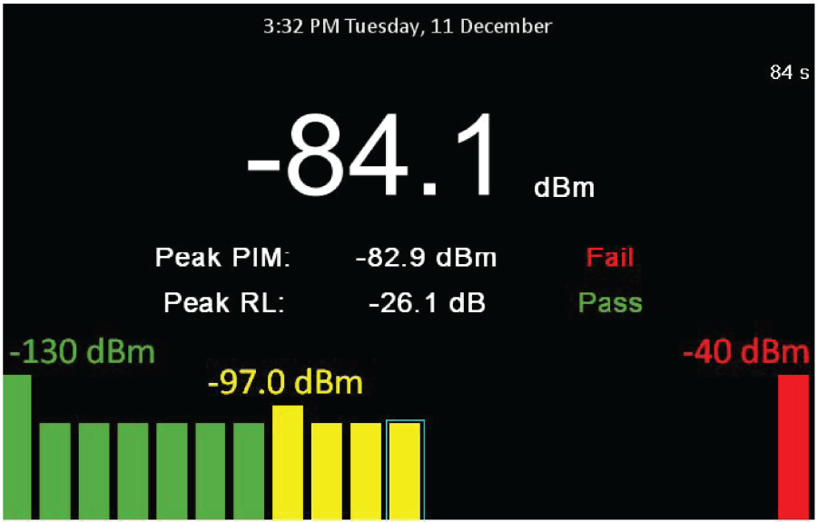
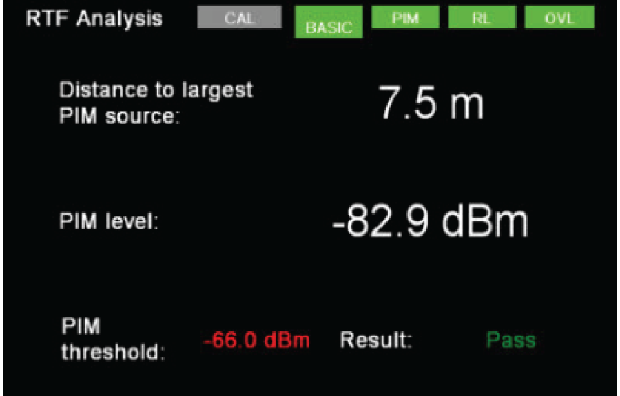
With an RTF Module attached, the user software provides four different views the operator can use to analyze PIM faults at the cell site. The "Basic" view clearly identifies the distance and magnitude of the largest static PIM fault on the line. For fastest results, Kaelus recommends methodically eliminating the largest PIM fault and repeating until all static PIM sources have been removed. Once the static PIM sources are removed, the operator can proceed to dynamic PIM testing to certify that the PIM performance is stable and robust.
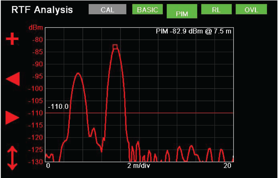
With a single button push, the operator can switch to "PIM" view to see the relative magnitude of all PIM sources on the line. A marker function is provided allowing the user to jump from peak to peak displaying the magnitude and distance to each PIM fault. Kaelus' RTF solution utilizes proprietary enhanced resolution algorithms that enable the user to resolve closely spaced PIM faults that a standard FFT analysis can not see.
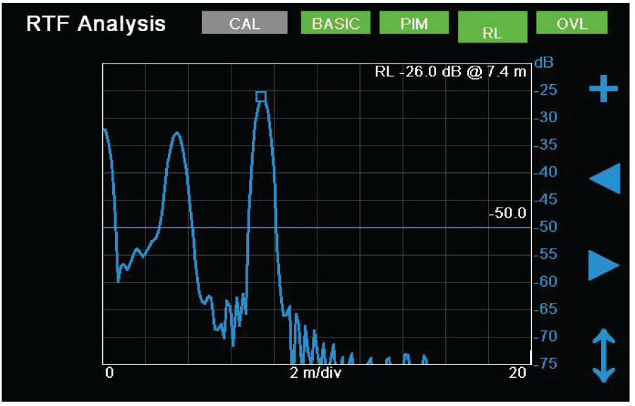
With a second button push, the operator can switch to "RL" view to see Return Loss vs. distance. As with the PIM view, a marker function is provided to display the magnitude and distance of each Return Loss peak.
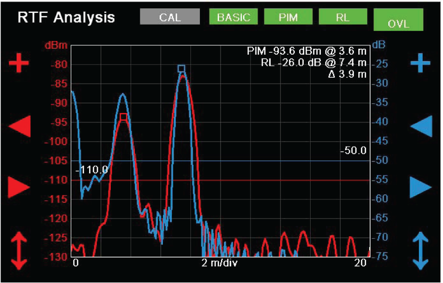
"OVL" view overlays Return Loss vs. distance and PIM vs. distance on a single screen. The user can independently set markers for both PIM peaks and Return Loss peaks and measure the relative distance between faults. Electrically long devices such as filters or TMAs, and changes in velocity factor caused by jumper cables vs. feeders can reduce the absolute accuracy of individual distance calculations. Since these errors impact both the PIM and Return Loss calculations equally, the relative distance between faults is typically more accurate than the individual distance calculations. Using the relative distance of a PIM problem to a known Return Loss peak allows users to locate faults on the line with more precision than with PIM vs. distance alone.
| 제목 | 다운받기 |
|---|---|
| RTF 시리즈 데이터시트 | 다운로드 |