


New Products
2.92 mm(K) Connectors
- DC to 40 GHz
- Air Dielectric
- Mechanically Compatible with SMA, 3.5mm Connectors
- Captivated Center Contact
Introduction
GigaLane 2.92mm Connectors are precision connectors for optimum RF performance up to 40 GHz. 2.92mm connectors feature high mechanical stability and excellent repeatability. The connector is compatible with 3.5mm and SMA connectors.
It is applicable to military and telecommunication application.
기가레인 2.92mm 커넥터는 최대 40 GHz의 최적 RF 성능을 위한 정밀 커넥터입니다. 2.92mm 커넥터는 기계적 안정성이 뛰어나고 반복성이 뛰어납니다. 이 커넥터는 3.5mm 및 SMA 커넥터와 호환됩니다. 군사 및 통신 응용 분야에 적용 가능합니다.
기가레인 2.92mm 커넥터는 최대 40 GHz의 최적 RF 성능을 위한 정밀 커넥터입니다. 2.92mm 커넥터는 기계적 안정성이 뛰어나고 반복성이 뛰어납니다. 이 커넥터는 3.5mm 및 SMA 커넥터와 호환됩니다. 군사 및 통신 응용 분야에 적용 가능합니다.
Interface Standards (MIL-STD-348)
Specification
| Frequency | DC~40 GHz |
| Impedance | 50 Ω |
| VSWR | 1.25 : 1 to 40 GHz |
| Insulation Resistance | 5000 MΩ |
| Dielectric Withstand Voltage | 1200 Vrms max |
| Contact Resistance - Outer Conductor - Inner Conductor |
2mΩ max 3mΩ max |
| Insertion Loss | 0.3 dB max (@ 40 GHz) |
| RF Leakage | -90 dB |
| Power Handling | 80W (@ 2 GHz) |
Mechanical
| Mating Cycle(Durability) | 500 |
| Recommended Mating Torque Proof Torque |
Proof Torque 0.9 ~ 1.13 Nm / 8 ~ 10 lbs 1.7 Nm / 15.0 lbs |
| Coupling Nut Retention Force | 270 N / 27.7 kfg / 61 lbs |
| Center Contact Retention Force | 4 pound (axial) |
Environmental
| Temperature | -40˚C to + 125˚C |
| Thermal Shock | MIL-STD-202, method 107, condition B |
| Corrosion(Salt Spray) | MIL-STD-202, method 101, condition B, 5% salt |
| Vibration | MIL-STD-202, method 204, condition D (20G) |
| Moisture Resistance | MIL-STD-202, method 106 |
Material
| Body | Stainless Steel | Passivated |
| Center Contact | Beryllium Copper(BeCu) | Gold Plated |
| Insulator | Engineering Plastic | ㅡ |
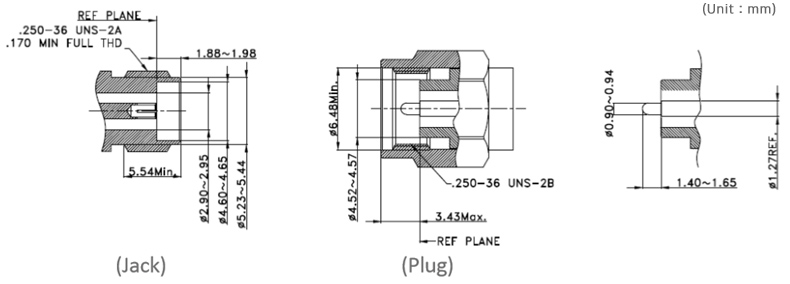
JACK (Female)
PLUG (Male)
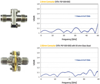
Test Result of 2.92mm Connectors
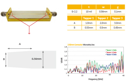
A very reliable connector can still increase VSWR if it does not match impedance when it is connected. Therefore, 50ohm microstrip line structure is recommended to get a maximized future advantage with PKF series connector.
Design Guide (Microstrip to coax)
Test result of Back to Back
Installation of 2.92mm Connectors with Glass Bead
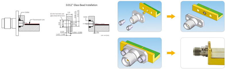
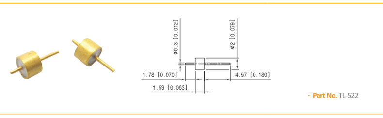
Hermetic Seal (0.012" Glass Bead)
Tel : +82-70-7872-0701Fax : +82-2-2167-3801
2F, ACE hightech city, 775, Gyeongin-ro, Yeongdeungpo-gu, Seoul, Korea
2F, ACE hightech city, 775, Gyeongin-ro, Yeongdeungpo-gu, Seoul, Korea